Categories
Assignment 5

Assignment 5 – Steve

As Paranyushkin observes, the ability to visualize relationships between multiple dimensions of data “unlocks the potentialities present” by seeing data in “a non-linear fashion, opening it up for interpretations that are not so readily available” (Paranyushkin 2011).  Gephi, a network analysis and visualization tool, is invaluable in helping researchers generate detailed network graphs and metrics that may otherwise remain hidden in data or text.  By manipulating different options within Gephi, a variety of relationship maps can be created which emphasize different aspects of the relationships within the data.  This flexibility opens the door for researchers to explore new meanings and interpretations of the data.

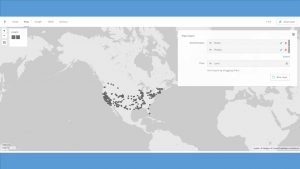
The process my partner (Katie) and I took to learn about Gephi included viewing video tutorials found on the Gephi website (https://gephi.org/) and reading the training collateral that walks users through ‘starter’ projects from beginning to end (e.g., http://www.martingrandjean.ch/gephi-introduction/).  These seem helpful for novice users like ourselves, though Gephi is an advanced tool which we feel expects users to be acquainted with the concept and metrics behind network graphs as a prerequisite.  Although, I believe it is important to state that even with the help of these tutorials, I sometimes could not get Gephi to work properly on my computer.  Luckily, my partner Katie’s laptop was capable of acquiring the visualizations we wanted.  (Therefore, most of these screenshots come from her laptop).

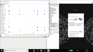
Once we were comfortable enough to begin the process of using Gephi, we built the nodes and edges data, which is the cornerstone for driving graphs and statistical metrics within the application.  The data used for this project consisted of a subset of records produced by the 18th century Moravian missionary on Native Americans being baptized in the Mid-Atlantic states (each missionary, as part of their spread of Christianity, wrote down key data on each person baptized including names, where, when, location, family relations).   For our edge data, we focused solely on the family relationships within the baptized Native Americans. The process of building the edge data was time consuming, because it involved reviewing records and creating links manually. Once this was completed and loaded into Gephi’s Data Laboratory, a network graph was immediately produced, below.

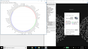
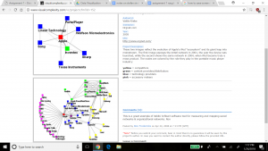
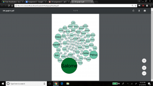
As the Gephi training modules explain, this initial graph is meant to show only a basic network model, and at this point it is up to researchers to explore relationships in more detail and variety using the power of Gephi’s visualization options. As a first step, we chose to produce a view that overlays the node labels onto the graph so that the context about what the graph represents is shown, and colored the edges to present a different aesthetic, below.

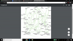
For the next view, we expose another dimension of the data by including the ‘nation’ property.  This view helps visualize if any one nation was more likely than others to have family members baptized together (rather than individually).  This would help explore the importance of close family in the spread of Christianity across the Native American nations.  Katie and I made the nation visible by selecting the ‘partition’ option under the ‘appearance’ widget, and selected ‘nation’ as the attribute to color, with the result below.

The edges in the graph are now colored by nation – the top 3 nations represented by the family relationships in the graph are Wampanog (41.6%, purple), Delaware (31.5%, green) and Mahican (20.2%, blue) – which together represent 93.3% of the total population in my dataset. This would indicate that family is an important aspect to the spread of Christianity at the time.

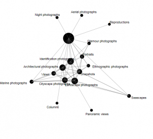
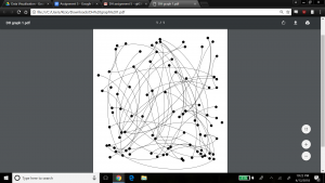
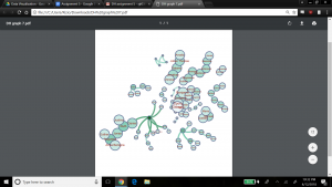
To spatialize the network, different layouts are possible within Gephi. The ForceAtlas 2 layout makes communities within the network transparent by bringing closer together nodes that are connected, and pushing out unconnected nodes. The result is below.

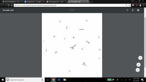
This graph is interesting because it clearly shows small pockets of members grouped together in family units, with little connection between them.  This might not appear to be a good sample of a network model with many relationships. However, I believe this visualization might well be expected from the data, since the data focuses on family relationships between the people who were baptized in my dataset.   Selecting the Force Atlas layout presents a nicer aesthetic I believe, as shown below, to see the groups of families who were baptized, and how these families have little to no family relationship to each other.

We kept the ‘nation’ aspect colored in this visualization, which indicates that most families are made up of members from the same nation, but interestingly there are a few families with members from different nations. Perhaps this shows that baptizing helped bring more people across nations together, or that families who already were made up of members from different nations were more inclined to be baptized.

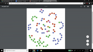
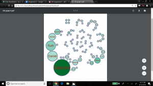
Next, we explored the statistical metrics embedded within my data – degree, modularity, and betweenness. In our dataset, there are 89 nodes and 70 edges. Degree is a measure of how many edges a node contains, which explains its connectedness to other nodes in the dataset. We wanted to visualize the nodes scaled to their degree – that is, the nodes with most relations would be the largest. To do this, we kept the layout as Force Atlas, selected the ‘nodes’ tab under the ‘appearance’ widget, and selected ‘ranking’ to be ‘Degree’. We entered a large range for scaling the nodes to emphasize results (since we expected most families to be somewhat of the same size) – min size was 5, max size was 200. The result is below.

Salome has the highest degree which means she has the most family members connected to her, followed by Petrus, Caritas, Ruth, Augustus and Gideon. We also ran the Average Degree report in the ‘Statistical’ tab, which produced a value of 1.57. This would indicate that my dataset contains mainly small family groups on average, or larger families balanced by a fair number of individuals with no family connection. If we refer back to graph 4, which shows clear communities of small families, that could lead us to believe the network contains mainly groups of small-sized families.

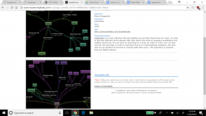
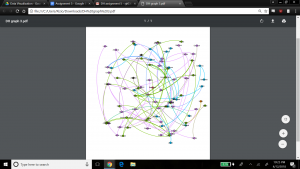
The next metric is modularity which shows the community structure within the network. Nodes connected together, rather than with the rest of the network, are viewed as being in the same community. Regarding modularity, Paranyushkin states that a modularity measure greater than 0.4 indicates that the partition produced by the modularity algorithm can be used in order to detect distinct communities within the network. It indicates that there are nodes in the network that are more densely connected between each other than with the rest of the network, and that their density is noticeably higher than the graph’s average (Paranyushkin 2011). For this statistical calculation, we ran the ‘modularity’ report which showed a modularity value of .9, and number of communities equal to 21. Confirming Paranyushkin’s view, this network, with a modularity value of .9 (which is greater than .4) does contain distinct communities (a total of 21 according to Gephi’s count) within the network as I previously noted based on the visualization in my fourth and fifth graphs. The graph below visualizes my network’s modularity and was produced by ranking on ‘modularity class’ in the ‘appearance’ widget, using the ForceAtlas2 layout.

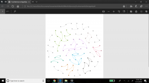
In terms of comparing different ways to view modularity, below represents another community visualization, this one produced by selecting the Fruchterman Reingold layout, which seems ‘prettier’ than graph 7.


The last metric we revealed in Gephi is the betweenness calculation. Betweenness indicates how often a node appears on the shortest path between any two random nodes in the network. The higher the betweenness value, the more central or important the node is of being a connector for the entire network graph. Gephi calculates the betweenness centrality measure under ‘Network Diameter’ option in the Statistical tab. Gephi indicated that my graph has a Network Diameter of 8. To visualize the betweenness centrality, Gephi enables node resizing according to their betweenness value – the more central the node, the bigger its size. For this view we used the Force Atlas layout, and selected min size of 10 and max size of 100 for scaling the Betweenness Centrality metric. The result is below.

We also chose to add the betweenness values as label attributes for the nodes so we could read the actual measures Gephi calculated – Salome was the largest node with a betweenness value of 127, and Theodora (and others) had the smallest betweenness value of zero.

In terms of what did not work well within Gephi, I would say there are areas of maturity problems that linger in the tool.  For example, there were times when the application lost my work and I had to restart. In another case, I mistakenly removed the ‘Layout’ widget and it took Katie and I quite some research to figure out how to reinstate it.  However, on the whole, these glitches could be overlooked because Gephi is quite powerful. I found the relative ease with which graphs could be produced, along with their associated key metrics, most compelling. With a few clicks, we were able to visualize our data in new ways we would not have been able to do before.  This kind of tool offers researchers the ability to quickly identify new connections or ideas hidden in data that may open up the door for different research paths. As Paranyushking describes, unlocking new meanings within data becomes possible with a network visualization tool like Gephi because “it allows the text to speak in its multiplicity”.

Works Cited

Paranyushkin, Dmitry.  Identifying the Pathways for Meaning Circulation using Text Network

   Analysis. Nodus Labs, Berlin. October 2011.


Categories
Assignment 3

Assignment 3

The data I used for the Palladio exercise is the meta-data from the Charles Weever Cushman Collection of photographs (the CSV file is taken from the sample set), located at Indiana University.  I extracted about the first 3600 records from this data set and loaded into Palladio.  The first image I created using Palladio’s map tool was a geographical representation of where the photos were taken.

This output gave a good representation of the distribution of photos in the United States, but it lacked significant detail.  I performed the same graphing exercise this time using Google Fusion for comparison reasons.  For Google Fusions I uploaded the entire CSV file.  As shown in the figure below, the Google Fusion map provides more details automatically.  This includes the state boundaries, state names, and a clearer demarcation of individual photos.  On the other hand, both tools confirm generally identical results- photos were taken across the nation with a concentration in the west coast with very little in the central north.

Using Palladio, I then created a timeline view to visualize the number of photos taken over the course of Charles Weever Cushman’s journey.

This demonstrates the most active years in Cushman’s endevour (1952).  This shows he started slowly, hit a peak in 1952, and kept up the volume somewhat until he finished (through 1956).  This simple to use tool lets researchers get a sense of the time perspective of the data they are observing.

Next I used Palladio to create a network graph, which is a useful process for mapping a system of relations, which is up to researchers to define.  Network graphs can be useful to find otherwise hidden patterns or trends in data being researched.  For example, in the Cushman photo library, I created a network graph that showed the relationships of the kind of images depicted in each photo.  For this graph, I related “genre 1” to “genre 2” categories, which produces a map of the relationships of the kind of images that simultaneously occur in each photo.  For an additional layer of information, I chose the “size” option, which depicts the frequency of connections by the size of the network node between each genre.

In terms of Palladio’s ability to demonstrate Drucker’s notion of spatialization, I think the map view will be useful in triggering different ideas to research regarding the data being analyzed and its relationship to geography.   In this example, the results are simple – the map shows the locations where photos were taken.  However, with more complex data, there could be more interesting spatialization perspectives that can be discovered.


Categories
Assignment 2

Assignment 2 – Steve Rizio

For our data visualization project, Katie and I analyzed religious texts to unveil the potential similarities and differences between them. Thus, our corpus is constructed of the Christian Bible, Muslim Quran, and the Hindu Vedas. The digital text of the Bible was available for us with the installation of Jigsaw. For the Quran, our professor had a digital text version of it on hand and shared it with us for our research. The Hindu Vedas is the only missing piece of text we do not have in our corpus at this time. I do not believe this will be problematic because simply Googling “Hindu Vedas,” we are met with multiple search results for PDF versions. I only have to download and look through a few samples to make sure they can be processed and do not have too many errors.

(For clarity, I will be using Voyant for the Quran and Jigsaw for the Bible in the image examples below)

Here is an example of using the Scatterplot tool in Jigsaw. The two axes show words that connect with each other. I noticed that this view presents a few repeat words connecting with each other, which adds little value to our research (example: “Jesus” connects with “Jesus”). The concept of the Scatterplot tool however does seem promising.

This is the Circular Graph tool. I liked the interactiveness of this tool. When clicking on one of the entities, connections to other entities are automatically displayed (on the outer rim of the circle). This provides an easy way for researchers to visualize the connectivity between an entity and other entity groups. The same “repeat words” problem that we saw with Scatterplot appeared with this tool also. I think both of these tools would be especially helpful if the user makes their own custom entities. I noticed though while using these tools that Jigsaw did not have discreet grouping, which resulted in self-connectivity. This made it a bit harder to identify real connections.

Voyant’s Word Cloud tool produced these results. The Word Cloud tool offers researchers a fast approach to understanding key messages in a text, simply because it shows by size the words most used. It does not require intensive effort to understand the results – with just a glance, users quickly see the major points by observing the largest words. Looking at the cloud, it is not surprising that two words that refer to Allah are especially prevalent (“Lord” and “God”). However, I did find it surprising that an important biblical figure, Moses, appears many times in the religious text as well.

The Trends tool helped me identify something peculiar. “Shall” was used extensively more than any other word in the beginning, but it eventually died down to “normal” frequency. I think this highlights the usefulness of this tool. If I was close reading the Quran, I likely would not have noticed the changing frequency of “shall” in the text, but the Trends tool visualizes this deterioration quite nicely. For users whose research depends on examining word trends, this tool will prove indispensable.

I think Jigsaw and Voyant are exceptionally useful tools for data visualization. Personally, I like the concepts in Jigsaw better than Voyant, because they seem more rich and intuitive to me, but the “self connection” error is a major drawback. Although Voyant shows easier to understand data visualizations, it does not offer as much information as the tools embedded in Jigsaw. Most of Voyant’s results can be summed up as a word frequency visualization. Jigsaw shows connections between words in more ways than Voyant can, which may help researchers iterate and extend their investigation.

My process of corpus construction and data visualization through Voyant and Jigsaw verify Tanya Clement’s observation. This is because I can appreciate how the different ways I approach my queries can shape the result of any data visualization. Data visualization is indeed a varied and complex process, offering up a rich set of observations any researcher can jump on as results are presented. This is an interesting contrast to the research process anchored in surface reading a piece of text, which seems far more non-iterative in comparison.


Categories
Assignment 1

Assignment 1 – Steve Rizio

The first visualization from Visual Complexity.com that caught my eye is titled “iPod Ecosystem.”

It got my attention because it reminds me of my older sister’s stories about how she used to download and listen to music before Apple’s giant leap forward into shaping the music industry and song consumption.  Being born in 1998, I was always accustomed to Apple’s huge presence and popularity in the music market.

The two images juxtaposed against each other tell the story of the iPod’s transition into a mass market product quite nicely.  The first image depicts the initial business players in the days of 2001 – we see how sparse and limited Apple’s network connections were at the start.  The bottom image depicts the rampant market growth that resulted just three years later – the image shows how more diverse and full the iPod ecosystem business connections had become.

This other visualization, “visual i/zer”, lets users search for a song and see how different lyrics intersect with each other.

The user can do this by simply choosing and clicking on any keyword in a lyric to see how it connects with other lyrics using that same keyword.  It caught my attention because I think it is a good demonstration of how “iPod Ecosystem” in contrast fails to be engaging.

Although “iPod’s Ecosystem” is insightful, it leaves me wanting more. The lack of interactivity is a huge letdown as I would naturally want to click on the iPod’s connections to see specifically what each relationship in the ecosystem provides as a service or technology – similar to how “visual i/zer” works in dynamically showing the lyrical ecosystem.

The contrast between “iPod’s Environment” and “visual i/zer” highlights differences between static and dynamic visualization. It also proves Stéfan Sinclair, Stan Ruecker, and Milena Radzikowska points on how interactive visualizations are objectively superior to static visualizations.

“Interactive visualizations, on the other hand, aim to explore available information, often as part of a process that is both sequential and iterative. That is, some steps come before others, but the researcher may revisit previous steps at a later stage and make different choices, informed by the outcomes produced in the interim. In a pie chart, by contrast, a static, synchronic object, the visual subdivision of the whole into parts can be useful, but the format does not readily lend itself to experimentation.”

The static connections depicted in “iPod’s Environment” are fine, but do not offer users the ability to explore different parts of the network, like  “visual i/zer” allows.  The iterative feature of “visual i/zer” really hooked me in, and made me immediately feel that “iPod’s Environment” was flat in the info it offered in comparison.

My favorite visualization from the DH Sample Book was the one we looked over in class, the “Map of Early Modern London.”  This one is intriguing  because of its ability to show such a vast amount of information in an easy-to-use way.  Users can view the map through different perspectives by choosing the “locations by category” tool.  Bridges, churches, neighborhoods, etc. can be found and highlighted simply by clicking on them, giving users a lot of power and variety with their research options.   The format of its interactive user interface lets researchers explore freely and therefore draw their own conclusions about early London.   Like “visual i/zer”, the “Map of Early Modern London” reflects the best kind of visualization tools that our readings this week discuss.

Categories
Uncategorized

Two Bad Visualizations

This is one is bad because the visualization is not to scale with the numbers.  At quick glance, Microsoft Edge seems to be much faster than both its competitors.  In reality, the raw numbers are pretty close.


This one is bad because the graph gives no context whatsoever.  I have no idea what this graph is trying to convey.  Something to do with how each candidate won their respected states? It is hard to decipher.